


Grooving, parting, form turning: Grooving is one of the most demanding processes in turning operations. Unlike classical longitudinal or flat turning, the cutting edge works on the workpiece between two flanks during grooving and parting. These boundary conditions fundamentally shape the process. While the chip can flow relatively freely during longitudinal turning, the workpiece flanks limit the cutting edge on the left and right during grooving.

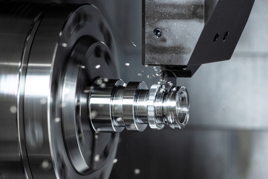
The chip primarily exits the cutting zone during grooving only upwards and against the feed direction. Therefore, the demands on tool geometry, chip formation, cooling, and process stability increase. Even small deviations can cause chip winding, increased wear, poor surface quality, or even tool breakage. Grooving is therefore much more than a simple piercing process.
Only the coordinated interplay of tool technology, coating, machine stability, clamping technology, and process control ensures stable results. The goal remains to shape the chip in a controlled manner, safely guide it out of the groove, and simultaneously achieve high tool life and reproducible machining results.
Importance of cutting edge geometry
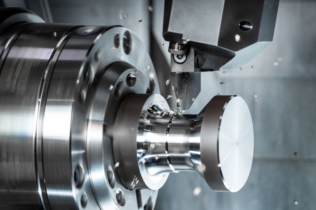
The cutting edge geometry significantly influences grooving and parting. Its main tasks are to guide the chips in a controlled manner and to shape them purposefully.
In chip control, the geometry produces short, manageable chip shapes such as spiral chip pieces, spiral chips, comma chips, tear chips, or crumb chips. This prevents chip winding and reduces process disturbances. In contrast, long band chips wind around the workpiece or tool, hinder chip flow, and worsen surface quality. At the same time, the geometry purposefully reshapes and rejuvenates the chip. This rejuvenation allows the chip to be safely guided out of the groove despite the enclosed machining situation. Without targeted chip shaping, wide chips form that rub against the flanks and damage workpiece surfaces.
The influence of geometry is particularly evident when comparing different chip guiding geometries. Ground, round chip guiding geometries often have little effect on the chip. The chip flows largely uncontrollably and forms long chip shapes. Geometries with pronounced chip shaping elements, on the other hand, produce short, controlled, and highly deformed chips. This controlled chip formation forms the basis for stable machining processes. Especially with stainless materials like 1.4305, the right geometry determines process reliability and tool life. Even at cutting speeds around 100 m/min and feeds of about 0.12 mm/rev, chip formation significantly influences the machining result.
Trochoidal grooving
Trochoidal grooving expands the possibilities of classical grooving processes. Instead of machining the entire groove in full cut, the tool moves through the workpiece on an overlaying path movement. This strategy reduces tool load. At the same time, chip transport improves because smaller chip cross-sections are created. This method offers advantages, especially for deep grooves or difficult-to-machine materials.
Typical process parameters are, for example, cutting speeds around 280 m/min and feeds up to 0.6 mm/rev. Minimum depths of cut of about 0.7 mm and maximum depths of cut up to 1.5 mm are used. The cutting angle typically ranges between 40° and 60°. Due to the lower engagement conditions, radial forces decrease. At the same time, the thermal load on the cutting edge is reduced. The method is particularly suitable for modern high-performance machining and large achievable chip volumes.
Importance of modern coatings
The coating of modern turning inserts influences cost-effectiveness and process reliability. It reduces wear, minimizes friction between chip and tool, prevents built-up edges, and allows for higher cutting parameters. At the same time, a suitable coating improves wear detection and increases process stability. Numerous influencing factors must be considered in the development of tool coatings. These include the chemical interaction between tool and material, edge rounding, the coating process, and the mechanical properties of the layer. However, the interplay of all components remains crucial. If geometry, substrate, and coating do not match, residual stresses arise within the layer. These can improve hardness and toughness but can also cause cracking or flaking.
The coating adapted to the process influences tool life. However, the layer must not be viewed in isolation. The interplay of the entire machining process remains crucial. Machine stability, workpiece clamping, tool holder, cooling strategy, and cutting parameters directly affect the performance of the cutting insert. Practical tests show that significant increases in tool life are possible even with adjusted coatings. At the same time, unsuitable combinations of geometry, coating, and process parameters quickly lead to premature wear. A process design always requires a holistic view of the entire machining system.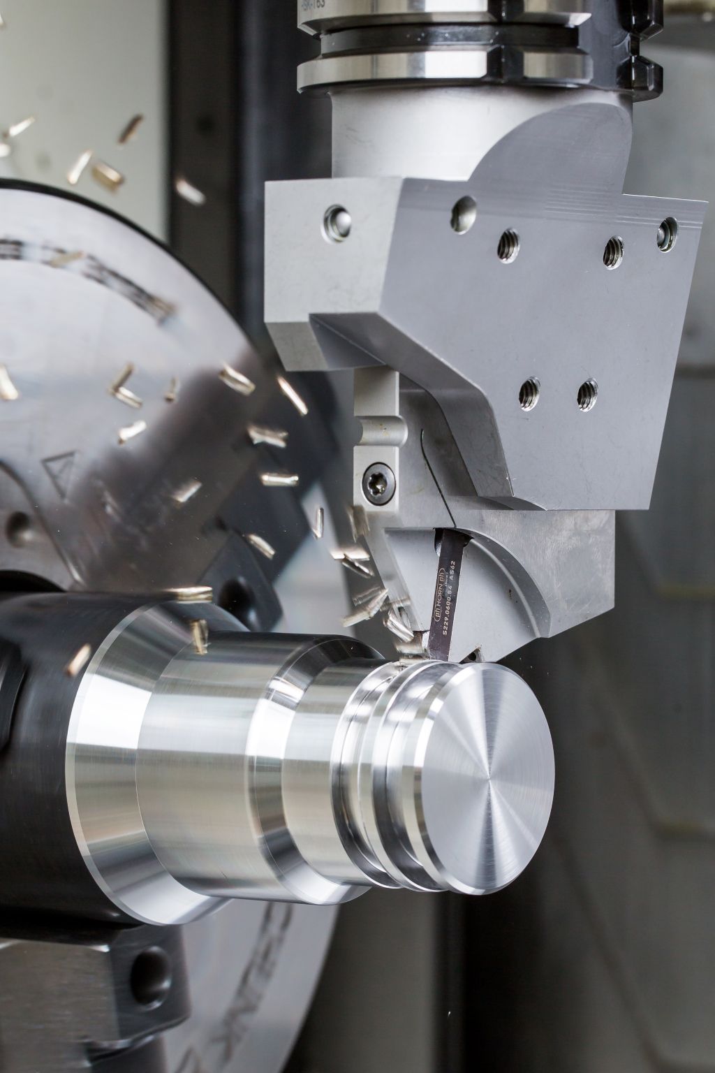
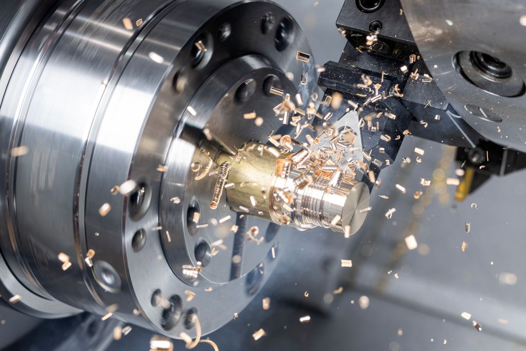
Cooling in the grooving process
Cooling plays a central role in grooving. On the one hand, it reduces the thermal load on the cutting edge, and on the other hand, the cooling medium actively supports chip transport out of the cutting zone. Especially when grooving into stainless materials, high temperatures arise. Practical studies show differences between various cooling strategies. With external coolant supply at low pressures, significant wear phenomena often occur on the chip surface. Increasing the coolant pressure significantly reduces wear.
Good results are achieved by systems that direct the coolant directly to the chip surface. Modern clamping holders with integrated coolant supply enable targeted cooling directly in the cutting zone. This reduces the thermal load on the cutting edge.
Furthermore, chip removal improves. Modern holder systems supply free and chip surfaces specifically through integrated cooling channels. By directly supplying coolant, the cooling medium lifts the chip early and transports it out of the groove in a controlled manner. Clamping holders usually have universal coolant connections via long holes or G1/8" connections.
Not only the coolant supply itself but also the composition of the coolant lubricant influences the chip removal process. Even small changes in the oil content of an emulsion can have significant effects on tool life. Practical examples show that increasing the oil content from 11 percent to 13 percent when machining Inconel 718 can double the tool life. Especially with high-temperature resistant materials, a higher lubricant content improves the friction conditions between chip and tool. This reduces temperature and wear while simultaneously improving chip formation.
Parting with X and Y axis
Parting forms the last machining step on the main spindle. Errors in this process lead directly to scrap or damage to the component.
Traditionally, parting is done over the X-axis. Here, the cutting forces act perpendicular to the tool holder. As the distance between the cutting edge and the holder increases, the lever arm grows, and the bending stresses and tendency to vibrate increase. When parting over the Y-axis, the direction of the resulting cutting force changes. A large portion of the forces is absorbed through the cutting speed, while only a small part acts through the feed. The resulting force is introduced into the tool holder at an angle of about 30 degrees. Consequently, the effective lever arm is significantly shortened. Additionally, chip flow improves as the chip is directed straight down into the machine bed.
The different force ratios directly affect the load on the plate seat. With assumed forces of 2000 N perpendicular to the cutting edge and 400 N radially, parting over the X-axis results in a significantly higher load due to the long lever arm.
When parting over the Y-axis, this load is reduced by about 30 percent. Consequently, the processes run more smoothly and with less vibration. Practical examples show that switching from X to Y parting improves both tool life and process stability.
In individual applications, the tool life could even be more than doubled with unchanged cutting parameters. At the same time, the noise level decreases. However, Y-parting requires that the machine and control support the necessary travel paths and processing strategies.
Form parting of complex contours
Complex contours, such as multi-tooth profiles, place high demands on the process strategy. One possibility is to gradually create the contour conventionally with a parting tool. Individual passes are programmed and processed one after the other. This method is particularly suitable for prototypes or small series. However, with large quantities, programming and processing effort increases significantly.
Alternatively, form parting tools enable the production of the complete contour in just one processing step. A specially designed form cutting edge generates the entire geometry at once. The advantage lies in high repeat accuracy and short processing times. However, the large length of cutting edges engaging simultaneously generates high cutting forces. These forces can cause vibrations, surface markings, or dimensional deviations.
Peeling form parting expands the classic form parting with a significantly more process-stable strategy. Here, the cutting plate typically sits at an angle of about 45° in the plate seat. The tool does not enter the workpiece radially but is guided tangentially past the workpiece. In this process, the individual form elements are created one after the other. Unlike radial form entry, the entire cutting width does not engage the material simultaneously. Measurements with force measurement systems show clear differences between both methods. In classic form parting, cutting forces of nearly 6,000 N can occur. In peeling form parting, the forces are significantly lower. The reduced loads ensure smoother processes, lower machine stress, and lower noise levels. Furthermore, the surface quality of the turned part improves.
Conclusion
Horn is considered a specialist in economical and process-safe parting turning. Key factors for stable processes are coordinated cutting geometries, modern coatings, targeted cooling, and high machine stability. Optimized chip formation and internal cooling significantly improve chip removal, surface quality, and tool life. Processes such as trochoidal parting turning or Y-axis parting reduce forces, increase process stability, and enhance cost-effectiveness.
Contact:


