


With the introduction of laser-cut rake angles, a completely new approach in design and manufacturing is entering tool development. Instead of traditional subtractive machining through grinding processes, laser cutting requires a negative construction, where tool geometries are specifically designed for material removal by the laser. This leads to increased design effort, requires specialized CAD processes, and imposes new requirements on data structuring.
“The integration of laser-cut spindle geometries into carbide tools marks a fundamental shift in design and manufacturing,” emphasizes Alexander Seifermann, head of design at the Mössingen precision tool manufacturer SIMTEK. “Where we previously primarily used grinding, today we often use laser cutting – with significant impacts on geometry, design, and application. Moving away from classical, large-area material removal – towards targeted and three-dimensional design of complex geometries in negative.”
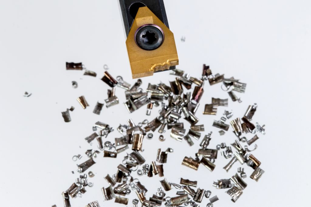
Technological advancement also brings entrepreneurial advantages: “The benefits are clear: We can produce highly precise, continuous cutting edge geometries – with optimized chip control and often expanded functionality,” adds SIMTEK managing director Norbert Seifermann. Despite initial hurdles that had to be overcome, the additional effort is worthwhile for most applications of custom tools. “The chip results are so convincing that we are now gradually incorporating the laser-cut geometries into our standard tool catalog.”
Constructive Change: From Material Removal to Negative Construction
Classical tool design was based on the principle of classical, large-area material removal. The design was intended to create the defined rake angles and clearance surfaces from a blank through grinding in manufacturing. Laser cutting, on the other hand, requires a completely different way of thinking – what will later be removed is now modeled.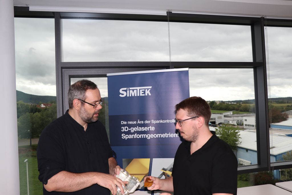
This “negative construction” involves significantly higher effort in CAD and generates several additional data sets per tool. The designer must precisely specify which areas are to be removed – a principle similar to tool manufacturing in injection molding, but much more complex in implementation. “Since laser cutting actually works with a negative, the constructed model serves merely for internal control,” explains design manager Alexander Seifermann.
“Manufacturing accesses the negative model directly, places it virtually on the cutting edge, and then precisely removes the material that was previously defined in the design.”
Laser cutting opens new chip spaces – but imposes higher demands
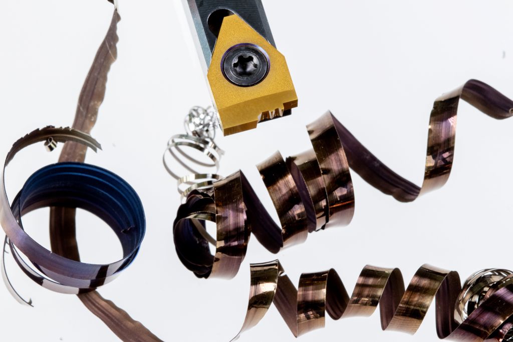
Laser-cut geometries enable highly complex structures: savings, recesses, bumps – everything is planned in three dimensions and implemented precisely. This creates new possibilities in chip control and tool optimization. At the same time, however, the demands on design increase: it requires solid know-how and a significantly tighter coordination process with the customer. Additionally, the CAD programs used by SIMTEK are only limitedly designed for this process – special working methods are needed to ensure clean transitions and error-free geometries. Alexander Seifermann and his team are aware of the challenges: “What we could still solve through experience and standard forms in the grinding process becomes a constructive challenge in laser cutting.
The demands on CAD, manufacturing, and customer communication are significantly increasing – and with more than 3,500 different customer-specific new developments per year, this is no small feat. At the same time, we are opening up completely new possibilities with laser-cut geometries: better chip control, longer tool life, more stable processes, and the integration of multiple machining steps into a single tool.”
Expertise from Experience
The entry into laser cutting of spindle geometries was a laborious learning process at SIMTEK – through trial and error and experience, a profound expertise has developed over the years. Today, both special and standard tools can be equipped with laser-cut geometries. These tools offer enormous advantages in terms of chip removal and surface quality, especially in small parts machining, with copper, aluminum, or other lead-free materials.
However, there is often still a need for clarification when introducing laser geometries. In this regard, the experts at SIMTEK provide consulting support to their customers and demonstrate the advantages that a laser-cut geometry brings. In these cases, the planned geometry is first visualized and explained to make the constructive intention transparent. This coordination process usually leads to follow-up questions and may extend the approval process somewhat, but it also ensures increased understanding and ultimately better results in most cases.
Laser cutting does not always mean the same thing
In conversations, it is occasionally pointed out that laser cutting of tool geometries has been established for years. However, it is important to differentiate: While this technology has already proven itself in the field of PCD tools (polycrystalline diamond), laser cutting of carbide – especially in the context of tools for microproduction – poses a significantly greater challenge.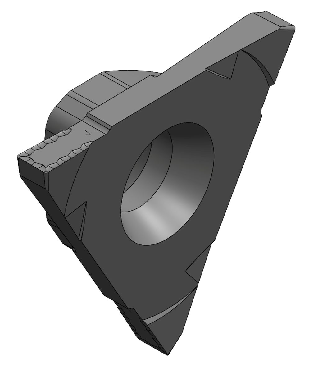
Due to technological reasons, materials behave differently during laser cutting: PCD particles decompose to graphite at around 700°C. Under oxygen, oxidative degradation and decomposition begin at about 600°C, while under vacuum, decomposition is delayed until about 1300°C. The graphite decomposes, becomes increasingly unstable, and can be relatively easily removed. “This process primarily begins at the grain boundaries, which are particularly important in cutting tools – this is often where the cutting edge or defined chip guiding step shape is located,” specifies Alexander Seifermann. In contrast, the melting point of tungsten in carbide is around 3400°C, and the boiling point is even over 5000°C. At these temperatures, however, other binder components such as cobalt and carbon already evaporate – making machining significantly more difficult.
After SIMTEK publicly launched the laser-cut geometries for the first time at AMB 2024, other manufacturers have now also jumped on the bandwagon. “We were aware that other tool manufacturers would intensively work on the laser topic now that they have seen that it works,” emphasizes Norbert Seifermann. Initially, these may have been simpler structures and far from the main cutting edge, but the geometries are now becoming more complex.
Additionally, sintered or injected ISO shapes are also being added. “We laser micro-geometries that can no longer be sintered or injected, laser-cut all the way to the cutting edge – targeted and with high precision.” The result is extremely sharp cutting edges. “What may visually appear to be a protective chamfer is actually an precisely defined, continuous angle that is accurately implemented and functionally tuned,” specifies design manager Alexander Seifermann.
Chip control requires dialogue – why communication is crucial
Lasered geometries open up completely new possibilities in machining - from targeted chip breaking to redirection and defined rolling. However, a close exchange between user and manufacturer is crucial to fully exploit these potentials. "The more we know about the specific application case, the more precisely we can design the geometry," explains Norbert Seifermann. This is particularly true for challenging materials such as C10 deep-drawing steel, lead-free aluminum, or copper. With coordinated parameters and lasered geometries, process-safe chip breaks can be realized - even where physical limits oppose complete chip breaking.
Practical information as a basis for optimal results
For a tool to realize its full potential, precise information about material, cutting values, and operating conditions is indispensable. In practice, it has been shown that small deviations in feed rate or material quality can have a significant impact on chip behavior. "If we know these parameters early on, we can optimally adjust the geometry to them," emphasizes Alexander Seifermann. For special tools, which are often used only in small quantities or for one-time applications, constructive feedback is particularly valuable. This allows successful geometries to be specifically further developed. "Close coordination with our customers ensures that we can develop practical solutions even without fully digital simulation - individually, reliably, and application-oriented."
From special case to standard tool
In contrast to individual custom manufacturing, internal test series can be conducted in the standard area at SIMTEK. Many of the standard geometries currently in use are therefore based on previously successfully implemented special solutions. "We have transferred the insights from special development, for example regarding full-radius-based geometries, into standard tools and established them there with great success," explains the head of construction about the procedure.
Especially with full-radius-shaped cutting edges, the laser-generated geometry is particularly effective: It enables uniform chip guidance across the entire cutting area - in contrast to conventional grinding, where the chip angle changes unintentionally depending on feed rate and depth of cut.
More efficiency through targeted geometry adjustment A specific application example clearly shows the advantage of lasered geometries: Where previously two tools and an additional holder were needed to perform radial notches and detachments, today a single lasered tool suffices, as practice shows. This not only saves tool changes and energy but also significantly reduces wear on the machine and tool.
Another practical example concerns the machining of an oil drain screw with multiple diameters and axial relief cuts. While the grinding process typically required two separate tools with limited geometry guidance for such tasks, laser cutting allows for the incorporation of cutting edges and chip angles in such a way that all work steps can be performed with just one tool - without compromising chip guidance.
Norbert Seifermann states: "With grinding, we would have introduced a chip lead step in the main chip direction - but what is the main chip direction in such a case? We would probably have chosen a 0° chip angle, which is extremely suboptimal. With laser cutting, however, the geometry can be precisely adapted to the process all around."
Constructive change with implications
While the design initially evaluated each new tool individually, this has now developed into a proven design principle. The first step: a circumferential, cutting-friendly geometry, tailored to the expected feeds. "This directly affects machine behavior: The tools run more smoothly, cutting forces decrease, chatter is reduced - and at the same time, higher cutting values can be realized," knows Norbert Seifermann.
A specific case demonstrates this effect: With a well-machinable material, switching to a lasered tool not only significantly improved the surface quality but also eliminated a complete reworking step.
Paris grind replaced by laser
Although chip control is often the main goal, higher cutting values, shorter processing times, and better surface qualities also speak in favor of using lasered geometries. A vivid example is the so-called "Paris grind" - a complex, ground hybrid geometry for turning and longitudinal turning operations. However, this geometry produced uncontrolled flowing chips and was more complicated for the tool manufacturer to produce. By switching to a lasered solution, SIMTEK was able to completely resolve the issue. The previous grinding variant has now been removed from the catalog and replaced by the lasered version.
Standard geometries with a system - and with limits
Despite all advancements, the standard area remains limited to universal geometries such as roughing and finishing. These must work for a variety of materials. This inevitably leads to conflicting goals: What works excellently for one customer may be unsuitable for another. A complete coverage of all application cases in the standard is therefore not realistic - here, the special tool remains the better choice.
Laser cutting by eye - economy decides
Despite technological possibilities, laser cutting is not economically sensible in every case. Especially for small series or simple machining tasks, a lasered geometry may exceed the actual need. The decision should always be made individually, depending on the material, machining task, cycle and setup times, and expected quantities. It also happens that a lasered variant may impress, but a ground one fits better into the customer's cycle time requirements. The motto is therefore: Not everything that is technically possible should be lasered - but only what pays off economically and reliably in the process.
Conclusion: From special case to series-capable solution
Laser cutting allows tools to be precisely tailored to specific customer requirements - for example, through circumferential geometries for turning and detaching processes. This reduces tool changes, saves processing time, and increases process reliability. Even previously difficult-to-manage problems such as tangled chips in thread relief cuts or built-up edges at negative chip angles can be successfully solved with lasered geometries. What began as an experimental approach at SIMTEK is now an established technology with clearly defined processes. The lasered tool geometries provide reliable chip control, high tool life, and open up new possibilities in tool development. For around 80-90 percent of applications, 3D-lasered tools offer a realistic - and often superior - alternative to conventional grinding - both technically and economically.
Author: Ralf M. Haassengier
Contact:


